Research
The $15 Servo Rabbit Hole: STS3215 Servo Hacking
16 min read
Introduction - FeeTech STS3215
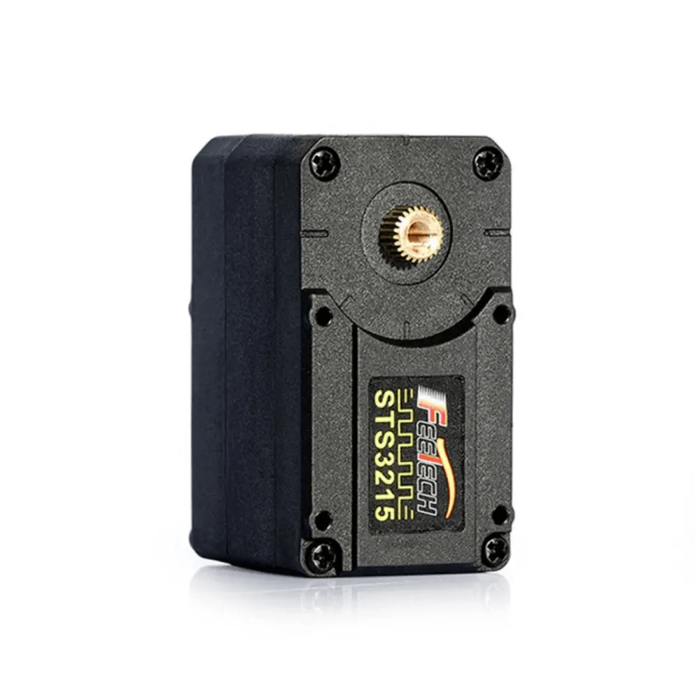
Leading up to the our online launch event, we increasingly used and got familiar with FeeTech’s STS3215 Magnetic Encoding Servo (hereafter, “the servo”). Six of these make up a vanilla SO-101 arm, and we chose to use them in our custom release arms as well, mainly because they are widely used by hobbyists and reasonably field-tested.
As we dug deeper, we started pushing against assumptions about the servos that went far beyond their documented behavior. We spoke directly with FeeTech about some of these constraints and were explicitly told that what we wanted to do was impossible.
That answer only made us more interested. The constraints turned out to be breakable, but not in the way the servo was designed to be used.

Along the way, we learned to:
- Assign IDs to a fully assembled, daisy-chained arm.
Every servo ships from the factory with ID=1, so once multiple factory-default servos are connected to the same bus, there should be no way to distinguish or address one without addressing all of them. The race condition we discovered broke that assumption: it gave us a primitive for selectively targeting an individual servo among otherwise identical devices on the bus. We used it to assign each servo its correct ID without disconnecting anything, and then automated the entire procedure. - Diagnose servo failures by touch, sound (and smell..).
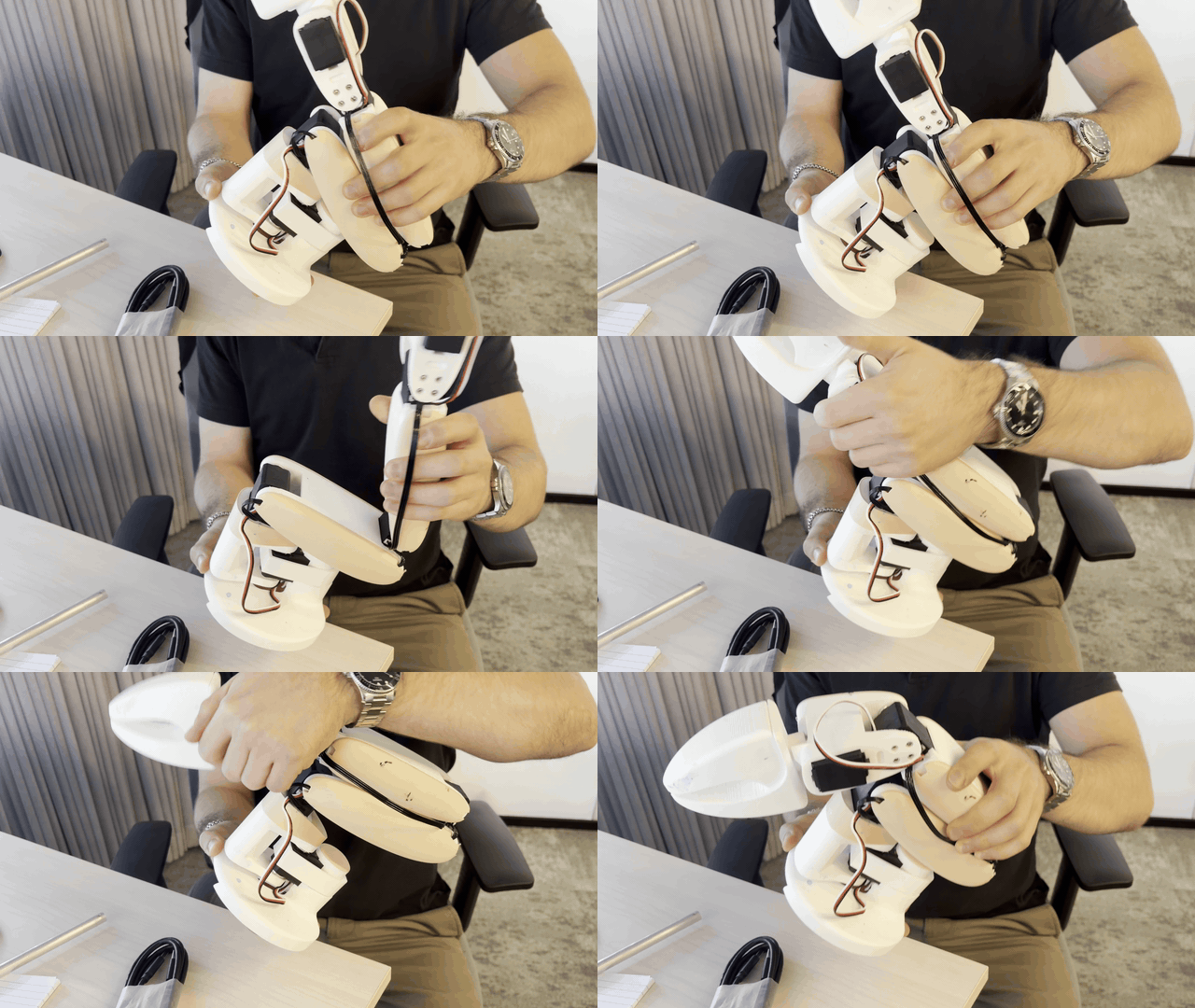
Slowly moving joints “physiotherapy style,” feeling their resistance, listening to the gearbox, and occasionally smelling the servo became a surprisingly effective way to identify failure modes. - Run Formula 1 style (arm)pit stop.
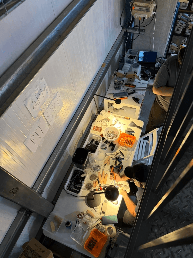
We got fast at tearing down, repairing, cannibalizing, recalibrating, and rebuilding arms in preparation for the release, where we expected arms to fall like flies. This included pulling servos from partially broken arms, renumbering them, calibrating partial assemblies, and rapidly turning broken arms back into working ones.
We wrote, researched, and vibe-coded and vibe-researched a small collections of utils which we are now releasing for anyone playing with SO101s to use.
Let’s start with a short overview of the STS3215, viewed pragmatically from a typical user’s viewpoint.
Then we’ll look in more depth at perhaps the most time-saving (and technical) primitive we got along the way - the ability to assign different IDs to servos already connected in a daisy chain, in assembled arms.
Finally, we will walk through the other utils included in the repo.
A Short Overview of the Servo
For reference (we will come back to this) - here is the STS3215 datasheet, summarised.
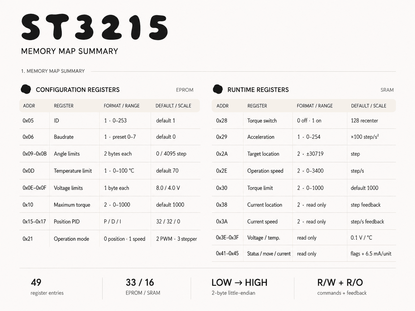
Some more fun info sources on this servo, (which are not that easy to come by) are:
- STS3215 register reference - a reference, useful for agents
- unofficial STS3215 firmware reimplementation - an unofficial white-box reimplementation, probably based on vibe-reverse-engineering of the firmware.
The servo contains a small board with an ARM 32-bit single-chip MCU, which you can communicate with using UART. The protocol is proprietary, and described here: FeeTech Smart Servo Communication Protocol
The packet format is roughly
0xFF 0xFF | ID | Length | Instruction | Param1 ... ParamN | ChecksumIn a regular SO-101 arm, the servos are connected in a daisy chain. Meaning each servo has 2 ports for "5264" 3-pin connectors.we verified that this is a multidrop bus - meaning even if the servo is mid-reboot, the UART still passes through.
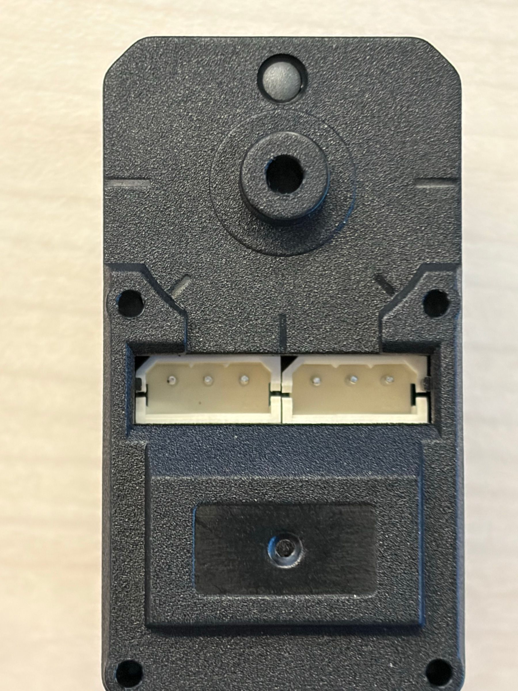
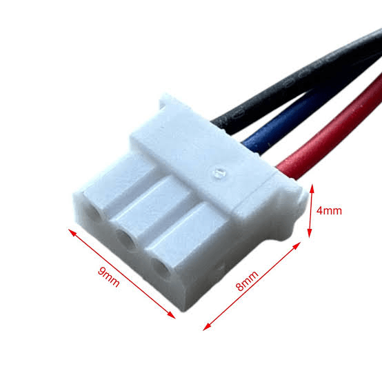
Notice - the only thing differentiating different servos, sharing the bus, is this ID field!
autonumber
The Problem
As described in the overview section, when we send a command on the shared UART bus, the way a servo decides whether it should act on it is by comparing the ID field from the packet to its own EEPROM value.
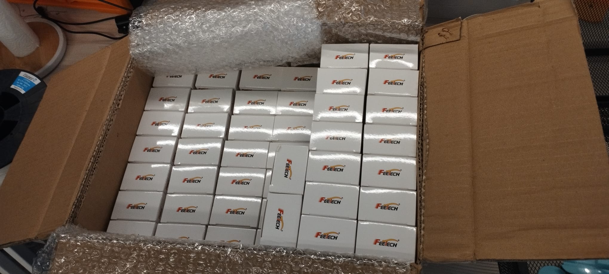
In preparation for the release we ordered, in bulk, a large amount of identical STS3215 servos from FeeTech. They all came from the factory with ID 1 (normally in an SO101 arm this is the shoulder pan ID).
The process of changing an ID is a WRITE DATA command to the EEPROM address where the ID is saved. Value is a byte.
We were now faced with 2 options:
- Before assembly of the arms, divide the shipment into 6 parts, and one by one connect them to reassign their IDs
- First assemble and wire the arms, and hope we can find a way to change servo IDs that doesn’t require taking the arm apart again
The main issue here: When multiple servos on the daisy-chain have the same ID, they simultaneously execute and answer your protocol packets. For example, write commands (such as changing the servo’s ID) effect all servos at once, and replies collide and cause corruption on the bus, making the response packets unreadable.
For example - trying to read the present position of a servo (a very common occurrence during an SO101’s operation), when we have two servos at ID 1, sitting at positions 2500 and 318:
READ Present_Position from ID 1   ->  ff ff 01 04 02 38 02 be

  1. ff ff 81 86 80 fe 81 bf     BAD   checksum fails
  2. ff 60 18 df e2 f7           BAD   framing destroyed
  3. 01 90 f6 0a fb              BAD   framing destroyed
  ...
 15. ff ff 01 04 00 fe 09 bf     BAD   well-framed, right ID — checksum fails
 16. ff ff 01 04 00 fe 09 bf     BAD   same again

     0 clean, 16 mangled, 0 silent
# ref: 0xFF 0xFF | ID | Length | Instruction | Param1 ... ParamN | Checksum
Look at packets 15+16 - here the read position is 0x9fe = 2558 which is exactly the bitwise OR of the two correct values.
You could think that we can just skip the servo discovery and blindly force a write:
WRITE lock=0    ff ff 01 04 03 37 00 c0  -> 41 a1 fd              CHECKSUM FAILS
WRITE ID=2      ff ff 01 04 03 05 02 f0  -> ff ff 01 02 00 fc     valid      <--
WRITE lock=1    ff ff 02 04 03 37 01 be  -> a1 a1 ff              CHECKSUM FAILS

PING old ID 1                            -> (silence)             no reply
final scan: {2: 'DOUBLE'}
But predictably we are now back at square one - they both have ID 2 ☹️
The Research Methodology
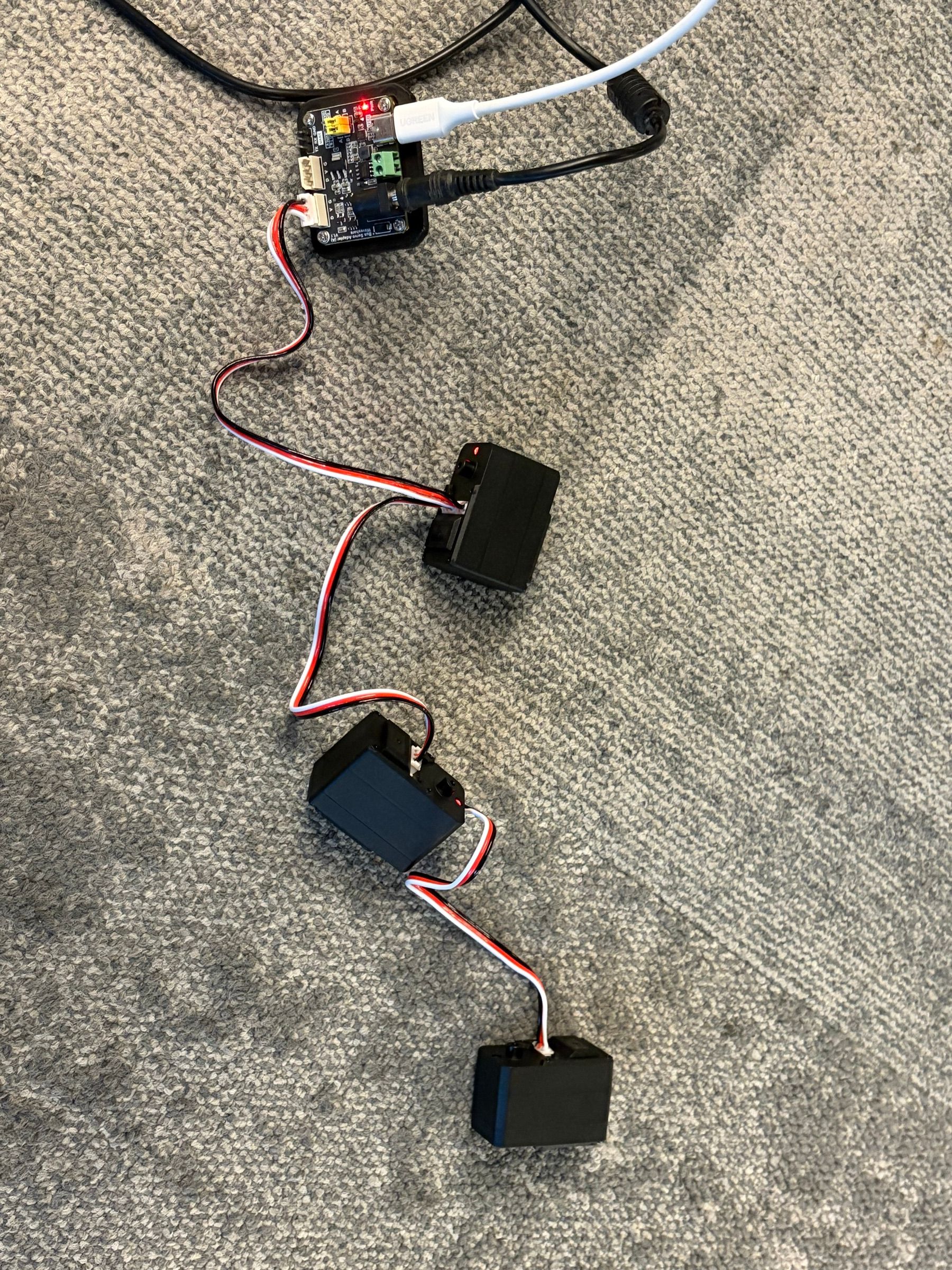
Matching the vibe of the times, and the fact that this was a short side-project and time was tight, we first just connected 2 daisy chained factory servos with ID 1, and let an agent auto-research the thing. The goal here is clear - don’t stop until you see 2 servos with different IDs on the bus.
This did not work (with the models at the time) autonomously. So we took inspiration from the security research world. Can we utilize some tight race condition / any other quantity which differs between the servos?
With this hint - we discovered an undocumented command (Instruction=0x8) which causes the servo to apparently reboot. Interestingly this command also exists in the unofficial STS3215 firmware reimplementation, but not in official FeeTech datasheets.
Pragmatically, we don’t really care what this command does. But potentially, during the brief time in which a servo is still in boot state, we can get clean answer from the other servo.
Here are the statistics of the timing of this boot, across 2 different servos.
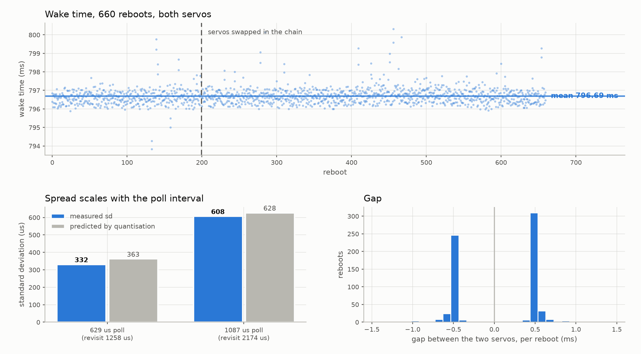
We notice two useful things here:
- The wake-time is very consistent, mostly up to 1ms, across both the 2 different servos and their position in the daisy chain.
- This is good, since we can “aim” our commands reliably to hit a window that comes at a predictable time after reboot.
- However - there is variance! There are times at which one is alive and the other is still booting.
- This is good, because it means said window exists 🙂
The Solution and Improvements
The solution, the implementation of which you can find in the servotools repo (servotools/src/servotools/split.py) uses this probabilistic wake time difference.
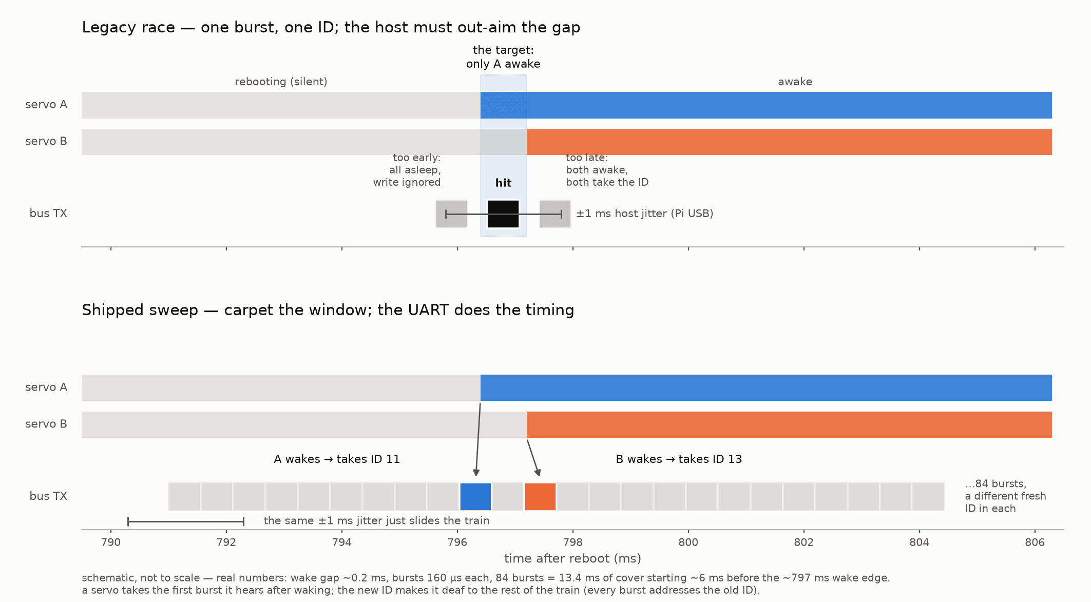
The naive way to exploit this is to just send reboot (0x8) to ID 1 (at this point, all chained servos), and then spam the message sequence for changing the ID: unlock EEPROM + write to the ID address. Assuming we hit the window during which some (but not all) servos booted, we now successfully “peeled” servos off ID 1. Rinse and repeat.
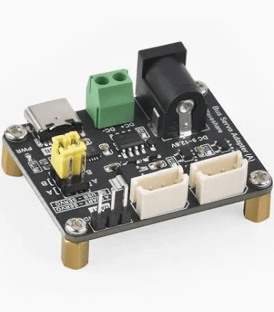
This worked from a MacBook, but not from the Raspberry Pi 5 which the arm assembly process was going to be using. The difference being that for some reason, Pi 5 has ~1ms of USB write jitter (we are writing to the Waveshare board via USB, and the Waveshare board turns it into serial for the servos). This jitter means we too often missed the race window, causing autonumber not to converge when run from a Pi.
The (very nice) fix was to build a big blob of many EEPROM unlock + ID write bursts, and give it all to the USB adapter in a single write() (sent before we expect the servos to start waking). Even better: We should have each burst in this blob write a different ID! This means that as each servo wakes during the boot window, it might land on a different burst, in effect peeling off multiple servos per write.
After we sent down a big blob to the Pi’s adapter (which is after the part of the flow causing the high variance jitter), it sends the bursts at low jitter and latency. Essentially - we passed on the responsibility of hitting the small race window to the hardware. These 2 improvements make autonumber work more reliably, with less coin flips. 🙂
Notice that even if we managed to give all connected servos different IDs, we still haven’t solved the ordering problem.
We managed to “strip off” servos and give them differentiating IDs, so that we can talk with each one separately. Ideally we would like to now somehow infer each servo’s position in the daisy chain. This would allow us to number them correctly (1-6, as for example LeRobot expects).
There are multiple solutions that pop to mind:
- Manual “wiggling” - have a human wiggle each servo, from bottom to top. Detecting the wiggle is easy (spamming position reads). This gives us the correct order the IDs should be in.
- Maybe wake time is correlative to position in daisy chain?
- Maybe voltage reads are distributed differently depending on position?
- Reboot a servo, see what servos still answer on the chain
- This assumes a rebooted servo makes all servos “behind it” on the chain inaccessible - which we observed is not true because the ports are literally wired together.
We decided not to increase complexity, and opted for the wiggling path.
Appendices
Servo Parameters We Explored
We approached this in a pragmatic way. During the PoC phase, we went back to the servo’s data sheet, and thought of parameters we could tweak (from the factory default) to get behaviour that suits the arm’s functionality best. For example, for the dueling arms, we wanted them to feel fast and snappy. For the painter arm, we preferred stability and precision (at least, relative to what these servos can offer. Keep in mind they are low cost, and not intended for very precise and repeatable tasks).
Of course, we played with the PID values. These are very common in robotics, and out of scope for this blog. Focusing instead on some FeeTech specific values:
Acceleration
Units are 100 steps/s^2. Since the servo position lives in 0-4095 , this is roughly 9 degrees of acceleration. As mentioned before, cranking this up is great for manual controls (where the user interface moves the bot directly), and for use cases where “overshooting” is dangerous (like approaching the painting canvas) we should keep it low.
Max_Temperature_Limit / Present_Temperature
Degrees Celsius, at which torque is disabled as a countermeasure. By default, its 70. You can read the current temperature off the Present_Temperature address.
Initially we were skeptical this would be a useful metric… Why would servo ever reach these temperature? Turns out during long continuous operation, especially for hard working arms like the duelists, the answer is all too easily.
We also continuously logged the present temperature of all arms as part of the observability over the fleet, and as part of the software-side protection - during demos we wanted to keep servo deaths to a minimum, and monitoring this metric was helpful.
Overload_Torque
80% by default - percentage of stall torque, at which if you dwell for Protection_Time (2s by default) you trip overload protection, which means dropping to Protection_Torque percent of the stall torque.
Kind of strangely, the FeeTech spec says this is “cleared by sending new position command”. This means that a buggy stack can accidentally completely ignore this mechanism (by streaming commands and not consuming the overload bit). See below what happens to such careless users.
This is a very useful metric to consume for software based protections, and also, if you are brave, to change for taking the SO101 to the edge without triggering the protection.
For your tweaking pleasure, servotools comes with the ability to easily change these values, by running servo defaults and changing config.py 🙂
Common Failure Modes We Encountered
When playing with these servos for a long time, we also saw them fail a lot. Mostly the failure modes were easily identifiable.
Shorted (burnt servo)
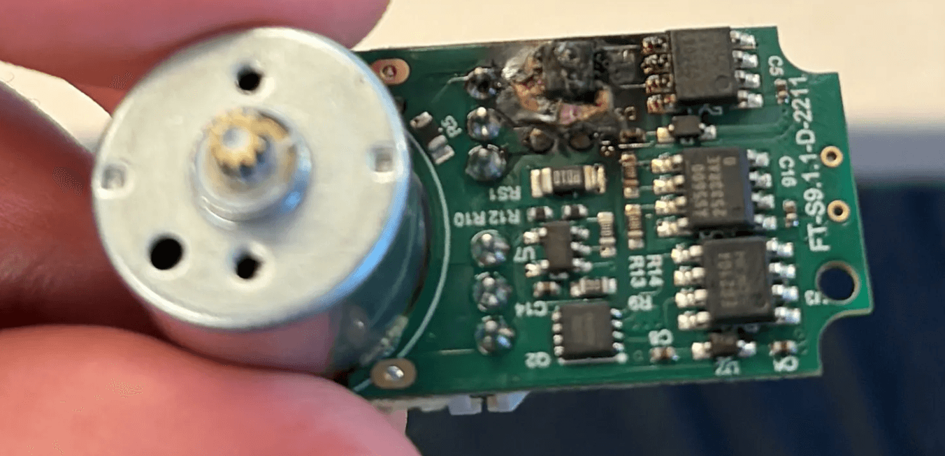
As mentioned before, our stack initially continuously wrote servo commands and never read the overload bit, which meant we just cleared the overload bit even when the servo is already experiencing high torque. Eventually, this led to the servo actually shorting.
We’re not sure about the exact mechanism here - the back drive / consistent stall against a surface might cause high current / voltage to propagate back through the servo, physically cooking the H-bridge MOSFET (see attached picture below). Whatever it is, we’ve seen servos go in a puff of smoke, with the unmistakable scent of burnt silicon. Multiple times.
A shorted servo spams the bus. This can cause all servos on the daisy chain to appear “stiff” (easily recognised by manually moving the arm). This is sometimes called “A babbling idiot”. A quick way to deal with this is to disconnect the daisy chain in a methodical way, until you isolate the problem maker. A quicker way is to smell each servo and find the obviously burnt one.
Gear wear
The gears of the servo, especially after being back driven or stressing against a surface (or dueling opponent…) can become worn down. Meaning some of the “teeth” are stripped or reduced.
This is easily recognized by a loud “clacking” noise during servo operation (because some teeth are skipped). Usually the servo can keep working properly (enough) in this state for some time, if you can ignore the annoying noise. However its usually the beginning of the end, and soon the servo needs to be replaced.
In a dire situation, this can be repaired by replacing the gear (maybe from a burnt servo?). Everything is pretty easily taken apart and put back together. But this is a bit overkill for a $15 servo.
Enigma Arm Calibration
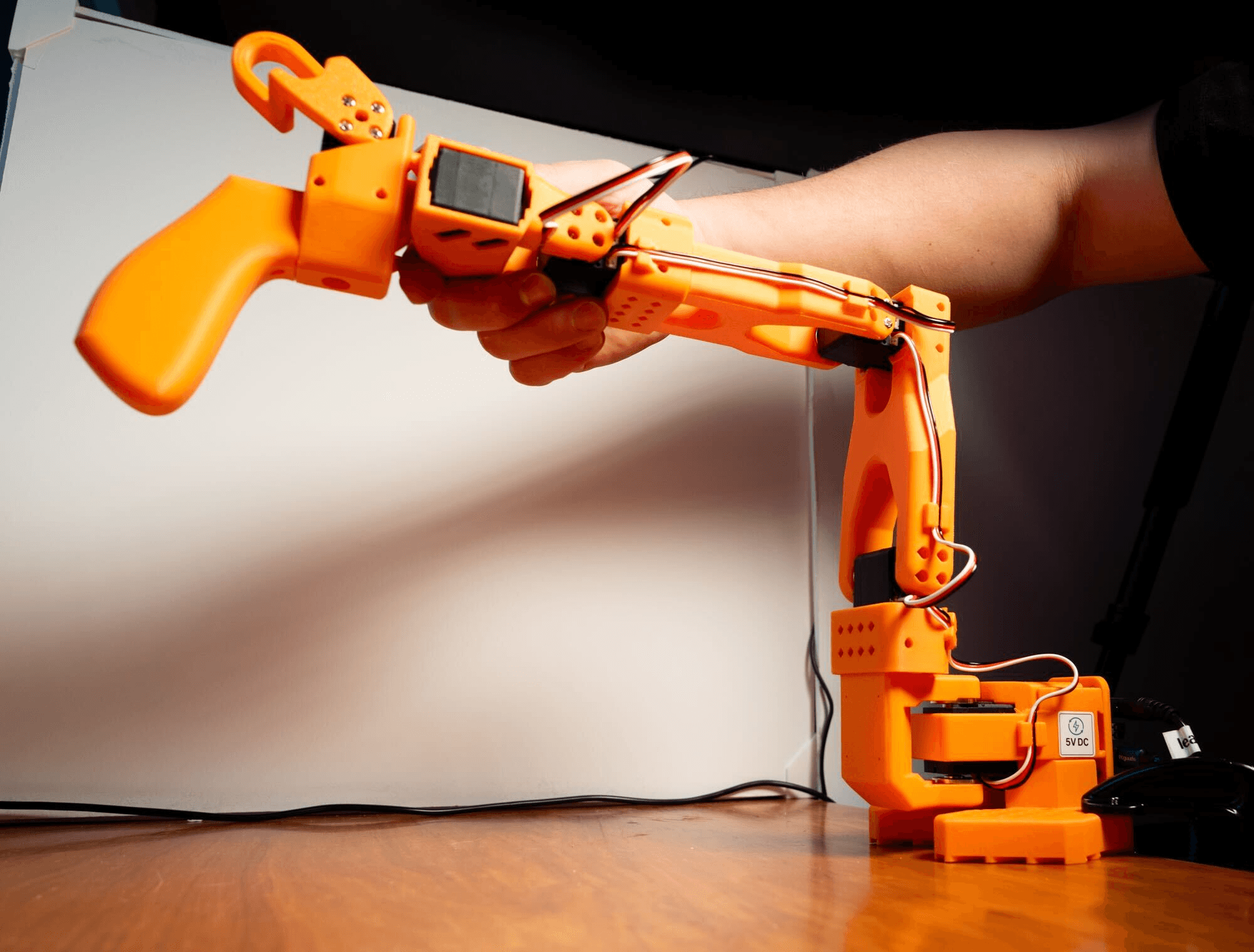
Anyone who has played with the SO-101 arm knows that LeRobot first expects you to calibrate the arm. Currently, this is an annoyingly manual process (especially if you do it for tens of arms..) in which you first move the arm to a “centered-position”, and then move it around to find the limits of all servos.
There is an open PR (as of writing this) that turns this to an automatic calibration process. We do something similar in our calibration script - the arm moves autonomously in a predefined order by commanding each joint to an unreachable target (+2 full turns), at very low torque. It detects the stop by polling the Moving value. In this way it finds the exact limits and midpoints (assumed to be the average+constant per arm design) per joint.
We also took this a step further - we wanted to get rid of the need for the serial-keyed calibration.json files, which LeRobot currently expects. Ideally, we wanted to be able to connect an arm to our stack - and have all relevant arm-specific data from the calibration be on the arm itself.
To achieve this we use the 6 servos’ EEPROM as the source of truth - specifically the homing offset value and the min/max position limits.
You can use this automatic, no JSON book-keeping script for yourself. Its in the attached repo (scripts/so101_calibrate.py).
Misc Utils
Also included in the attached repo are some quality of life helper scripts, that let us work quickly with servos. These were used “operationally” during the release itself, in the so called “robot pit stop” (AKA armpit stop), to quickly get worn / broken arms working again.
servo scan
A bus discovery tool. Sweeps baud rates and IDs to discover all servos on the bus. For each found servo, prints the important registers:
- temp
- mode
- torque
- PID
Helpful when you suspect a wiring / ID issue in an assembled arm, and as a sanity check for ready arms.
servo set-id NEW_ID
Assumes one connected servo, and does what it says 🙂
servo flatten
Mainly for testing - returns all discovered servos back to the default ID(=1)